

Piezoelectric generators are usually specified in terms of their short-circuit charge and open-circuit voltage. Short-circuit charge, Qs, refers to the total charge developed, at the maximum recommended stress level, when the charge is completely free to travel from one electrode to the other, and is not asked to build up any voltage. Open-circuit voltage, Vo, refers to the voltage developed, at the maximum recommended stress level, when charge is prohibited from traveling from one electrode to the other. Charge is at a maximum when the voltage is zero, and voltage is at a maximum when the charge transfer is zero. All other values of simultaneous charge and voltage levels are determined by a line drawn between these points on a voltage versus charge line, as shown in Figure 13. Generally, a piezo generator must move a specified amount of charge and supply a specified voltage, which determines its operating point on the voltage vs. charge line. Work is maximized when the charge moved permits one half the open circuit voltage to be developed. This occurs when the charge equals one half the short-circuit charge.

Mechanical inputs can be described as either forces or displacements acting on a specific point or area of the generator body. These forces may be either static or dynamic, low power (typically sensing) or high power (typically generating). If the force is oscillating and continuous, then the generator may be driven either at resonance or off- resonance (typically below resonance)
For long duration static forces acting on a piezo generator, such as a static pressure measurement, an understanding of creep, hysteresis and electrical leakage is useful.
Creep & Relaxation: Creep and relaxation are time dependent plastic phenomena resulting from piezoceramic grains slipping within the polycrystalline material upon application or removal of a load. When a constant load is applied and maintained on a piezo body, it will initially deform and then continue to deform (creep) over a period of time. There are three levels of creep: transient creep occurring immediately after load application; steady state creep characterized by a decreasing creep rate; and accelerating creep. At high drive levels, accelerated creep may proceed to the point where the piece finally cracks. Creep rates vary based on load level, temperature, and time. Upon removal of the load, the piece may slowly relax to its original equilibrium condition or retain a set.
Mechanical Hysteresis: Hysteresis is a lagging of strain values during stress cycling. When a polycrystalline piezoelectric body is deformed, part of the input energy is stored as elastic strain energy, and part is dissipated as heat due to small internal slippage mechanisms. Hysteresis appears as an offset in the strain level between the application and removal portions of a stress load. The size of the offset depends on the force level, cycle time, temperature, and materials used. For low stress levels encountered in small signal sensing, hysteresis is inconsequential, but for moderate and high stress levels it may be significant. Hysteresis is described as a percentage of the total strain and ranges around 15% for high stress levels. Voltage or charge production, which is strain dependent, is influenced by the mechanical hysteresis behavior. Hysteresis leads to non-linearity in transducer output.
Figure 14 demonstrates the typical mechanical hysteresis and creep behavior of a piezoelectric element such as a bender. Imagine a force applied to the tip of a cantilevered bending element. When the element has been at rest for some length of time (~ 1 day), it will reside at its equilibrium position, 0. Upon initial energization, the tip will move to position 1. After de-energization it will go to position 2. If it is allowed to rest for a sufficient length of time (~1 day) it will revert back to position 0 again. However, if it is forced again immediately, it will follow path 2-1. If the force is left on, it will creep along the path 1-1', and come to rest at position 2' after de-energization. A piece experiencing a full bipolar cycle will follow path 1-2-3-4-1. The size of the loop is time dependent and the area inside the loop represents the energy dissipation occurring during the cycle.

Electrical Leakage: After charge has been established on the electrodes of a piezo generator, it will immediately begin to leak away even though the insulation resistance is large. It will leak through the bulk of the piezo slab according to the relation for bulk resistance:
 |
(1.1) |
where ρ is the bulk resistivity of the piezo material in ohm-meters, t is the thickness between electrodes, and A is the electrode area. The value of resistivity for PZT-5A is ~1010 ohm-meters. Charge will travel along surfaces and over edges from one electrode to the other. Surface contaminants exacerbate this problem. Charge also drains through the input circuit. Lastly, charge may drain through the bleed resistor often placed across the electrodes to limit voltage swings due to pyroelectric (thermal) sources, triboelectric (surface friction) sources, and transient circuit currents. Eventually, the electrostatic charge will leak back to zero.
Overall, the behavior described above indicates why it is so difficult to design statically driven piezo sensing devices and why only dynamic force is generally measured.
Piezo is much more friendly to dynamic applications. Dynamic inputs may either be pulsed or continuous.
Pulsed Input Forces: For a short duration transient force, issues of creep and electrical leakage are insignificant since there is insufficient time for their behavior to occur. However, hysteresis still applies.
Continuously Alternating Input Forces: When the generator will be excited by an oscillating force, it is useful to be familiar with the following concepts:
Hysteresis: Hysteresis is a concern with oscillating forces because heat accumulates within the element for each cycle of operation. Heat accumulates from contributions due to mechanical losses described earlier and dielectric losses attributed to the phase lag between charge displacement and electric field. Low voltage piezo stacks are generally limited to < 1kHz operation at full loading due to heat buildup. Care should be taken in the design to account for heating caused by internal piezo losses as well as external system losses, such as strains within adhesive bonds, and friction at the mount or other points of attachment.
Mechanical Resonance: When a piezo body is acted upon by a periodic series of impulses, it will be set into relatively large amplitude vibration if the frequency of those impulses corresponds to the natural or resonant frequency of the device. This resonance is a manifestation of the trading back and forth of kinetic energy (moving mass) and potential energy (elasticity) in the oscillating body. At resonance, the amount of stored energy becomes very large compared to the excitation energy. For this reason, it is useful for achieving large voltages at low stress levels, and thus, for obtaining high efficiency. Because of the high amplitudes exhibited, care must be taken not to overstrain and crack the generator.
The resonant frequencies of a piezo generator depend on its dimensions, material properties, and the manner of mounting. The cantilevered piezo bending element, being very compliant, has the lowest fundamental resonant frequency per unit length of all configurations and mounting schemes. The piezo stack, being very stiff, has a high resonant frequency. Equations for determining the fundamental resonant frequencies for several generator configurations are shown in Table 4 on pages 38 and 39. These frequencies apply to unloaded elements only. Attachments to the element will add to the resonating mass and lower the resonant frequency.
Operating Frequency Band: Below resonant frequency, the strain of a piezoelectric transducer is nearly independent of frequency and proportional to the applied stress. Around the resonant frequency, strain rises rapidly to a multiple of its normal value. The amplitude and narrowness of the resonance depend on the internal and external losses acting on the generator. Above resonance, strain decreases steadily with the square of the frequency. Generally, for quasi-static transducers, a value of about 2/3 of the fundamental resonance marks the limit of the usable frequency band. For resonant applications, the useable frequency range is limited to a small band around the useful resonant modes. Figure 15 shows strain as a function of operating frequency.

It is useful to know how fast a generator element can respond to a force input. The fundamental resonant frequency, Fr, helps answer this question. A piezo transducer can follow a sinusoidal input up to its resonant frequency. Beyond this point, inertia prevents the transducer from keeping up with excitation. The time it takes a generator to travel from its zero position to full positive amplitude at its resonant frequency, is its response time, tr. This is 1/4 the time it takes the transducer to travel a full bipolar cycle (from zero to peak positive amplitude to 0 to peak negative amplitude back to zero). Thus,
 |
(1.2) |
The response time of a generator may be measured by driving it as an actuator with a low-level sinusoidal signal at resonance. For example, a generator having a resonant frequency of 500 Hertz, has a response time of 0.5 milliseconds under ideal conditions. In a practical setting, this response time is rarely achieved due to hysteresis and other losses. A more realistic estimate for tr is given by (18). Any mass added to the end of the generator will increase the response time.
 |
(1.3) |
An ideal mount permits the normal distortion of the entire active portion of the generator element, while at the same time preventing motion in certain directions at the mounting point or points. Generally, piezo generators are either bonded, clamped, or spring loaded to their mounting points. Mounts introduce some mechanical damping into the system since some of the energy from the generator distorts the mount itself. This may or may not be desirable.
Piezoceramic is very strong in compression but weak in tension. Bending elements always have one side in compression and the other side in tension, where the magnitude of stress increases linearly from the midplane to the outside surface. Therefore, the element is always limited by the maximum recommended tensile strength, generally considered to be in the range of 20-35 x 106 Newtons/meter2. From a strain point of view, the piezoceramic should not be allowed to strain more than 500x10-6 meter/meter in tension.
When the mechanical stress on a piezoceramic element becomes too high, again there is a danger of degrading the piezoelectric properties. Generally, compressive or hydrostatic stress levels of ~50 x 106 N/m2 are required to degrade PZT-5A if no other degrading influences are present.
A piezoelectric generator operating below its fundamental resonance can be treated simply as a capacitive element. It supplies, withdraws or stores charge. Ideally, this charge does not leak away. However, in practice charge may leak through the bulk material, over its edges, or through external circuitry.
A piezoelectric generator operating at resonance can be treated as a capacitor (having a value equal to the transducer capacitance) with a resistor in parallel. The power dissipated by this resistance represents the work which the transducer does on its environment or the internal loss occurring within the transducer.
The outer electrode surfaces of certain generator elements are electrically "live" in many configurations. For product or experimental safety, consideration should be given to insulating or shielding the electrodes, mount, and power input sections of the generator element.
The highest value of generated electric field is determined by electrical breakdown occurring either through the body of the piezoceramic sheet or over the its edges. Debris adhering to edges can initialize edge discharge at fields as low as 400-800 volts/mm. Continuous breakdown occurs around 3,000-4,000 volts/mm, usually at impurity or defect regions within the bulk of the material. This can lead to a short circuit across the sheet.
The bulk resistivity of piezoceramic is ~1012 Ω-cm. Therefore, electrical losses are minimal under static or low frequency operation. However, dielectric losses are significant at high frequency, under high load, and can lead to heating under high frequency /high power operation. The loss tangent, the ratio of series resistance to series reactance, for PZT-5A is ~0.015.
As mentioned earlier, under adverse conditions piezoelectric polarization may degrade, vanish completely, or be flipped around 180°. A strong electric field applied to a piezoceramic in a sense opposite to the original poling voltage will tend to cause depoling. The field strength necessary to initiate depoling depends on the material, duration of application, and temperature, but is typically in the range of 475 volts/mm at 20° C for PZT-5A under static conditions. Alternating fields may also degrade the piezoceramic, but the peak field level is higher because the duration is shorter before the field is reversed. A peak field of 600 volts/mm may be tolerated for 60 Hz operation at 20° C.
For each piezoceramic material there is a critical temperature, known as its Curie point, which represents its maximum operating temperature before suffering a permanent and complete loss of piezoelectric activity. In practice, the operating temperature must be limited to some value substantially below the Curie point because at elevated temperatures, depoling is greatly facilitated, the aging process is accelerated, electrical and mechanical losses increase, and the maximum safe stress is reduced. As a rule of thumb, a temperature equal to one half the Curie temperature is considered the maximum safe operating temperature.
Piezoceramic properties are temperature dependent, and thermal dependence varies markedly from one material to the next. Figure 16, Figure 17 and Figure 18 demonstrate the temperature dependence of d31, g31, and KT33 for PZT-5A, respectively.
An electric field is induced across the electrodes of a piezo generator when it is exposed to a thermal change. The induced field, E (volts/meter), is
 |
(1.4) |
where α is the pyroelectric coefficient in units of coulombs / m2 °C, ΔT is the temperature change, KT33 is the relative dielectric constant in the poling direction, and ε0 is the permittivity of free space. It is important in the design of a sensor to maximize the ratio of mechanical effect to pyroelectric effect.


It should be noted that a depoling voltage will be developed across a layer of piezoceramic when the temperature drops. This can happen during processing, testing, shipping, or normal usage. If a temperature drop is sufficient, over a time interval which is too short to allow charge to leak away, a voltage greater than the coercive field can result. This can degrade the original polarization causing reduced performance. It is always good practice to short circuit the electrodes of any piezo device during a cool down procedure.
Thermal expansion, ΔL, results in a dimensional change due to a thermal change, ΔT, according to the relation:
 |
(1.5) |
The coefficient of thermal expansion (at constant electric field), αE, of PZT-5A is ~ 4 μm / m °C. If positional stability is important, one must account for thermal expansion / contraction displacements over the temperature range anticipated.
Differential thermal expansions of adjacent assembly materials will cause moments, warping, and shifting. The standard 2-layer bending generator element has a symmetrical construction. Distortion due to thermal excursion should be slight. However, care should be taken in the design of the mount or any other attachments not to introduce thermal distortion. This is facilitated by properly matching the thermal expansion coefficients of adjacent members to that of the ceramic element.
The low signal values of the charge coefficients for operation at 4.2K are reduced by a factor of 5-7 times. The value of the dielectric constant decreases and the value of the coercive field increases, however. In general, piezo sensors work quite well at cryogenic temperatures where they have been used to monitor magnetic flux motions in superconducting magnets bathed in liquid helium. Cycling the transducer between these temperature extremes does not affect them adversely.
Thermal agitation can reduce the number of electric dipoles aligned during the original poling process. The higher the temperature, the greater the effect. Eventually, at the Curie temperature, the piezoceramic suffers a complete loss of piezoelectric properties and repoling becomes necessary.
Because piezo generators are solid state devices, they lend themselves to high vacuum operation. However, several issues should be understood. First, high voltage should not be generated across the electrodes during the vacuum pump-down process because of the low insulation resistance of air and nitrogen between the range of 10 to 0.1 torr. Arcing between electrodes is possible within this pressure range. Secondly, outgassing of the part is possible depending on construction materials. Generators to be used in high vacuum environments should have small cross sections of outgassing materials (primarily the adhesive). If bake-out is necessary, the transducer will have to be built to withstand solvents and bake-out temperatures.
Piezoelectric properties change gradually with time. The changes tend to be logarithmic with time after the original polarization. Therefore, the rate reduces rapidly with time. Aging depends on the ceramic material, manufacturing process, and ambient conditions such as temperature, vibration or shock. Pieces may be heated for a specified time to accelerate the aging process. It is common practice to model piezoelectric devices electrically to describe their piezoelectric, dielectric and electric properties.
It is common practice to use a lumped parameter electronic circuit model to simulate the interaction of piezoelectric devices with electronic circuits attached to them. These circuits are referred to as “equivalent circuits.” Equivalent circuits for piezo generators and vibrational sensors operating quasi-statically are simplest form of useful model. See examples below.
Figure 19 shows the equivalent circuit for a piezo charge generator. The only thing in this circuit that is accessible to the outside world is the two-terminal output interface. The value of Cp is the lab measured piezo capacitance and Rp is the measured internal DC resistance of the piezo device. Since the bulk resistivity of piezoceramic is of the order of ~1012 Ω-cm, Rc routinely runs in the giga Ohms and so is generally neglected. Q represents the charge generated by time dependent stresses exerted on the piezoceramic and can be calculated based on the design of the part, its mechanical mounting, and applied external forces. See Table 4 for formulas.

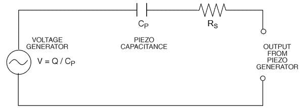
Since voltage can be calculated from the charge delivered by a piezo device according to the relationship that V = Q / Cp, Figure 20 shows a piezo device modeled as a voltage generator. Voltage output V is the open circuit voltage given in Table 4, and proportional to the stress applied to the piezo device Cp is the lab measured capacitance of the piezo sensor. Rs, the equivalent series resistance of the sensor, is frequently taken as zero. Unlike the Rp of the Charge Generator model however, Rs is not entirely internal to the sensor. Both surface resistance of the piezoceramic electrodes (typically sub-Ohm to 10 Ohms), solder connections, cable resistance, and connector contact resistance can contribute Rs.
The charge on a piezo sensor decays with time at a rate determined by its RC time constant. An RC circuit exhibits the exponential decay. Typically, charge is generated quickly. If the discharge time constant is large, it will not decay faster than the charging rate. Clearly, a long time constant is necessary if low frequencies need to be monitored
The signals from piezo sensors can be fed to meters, oscilloscopes, and circuits. The circuits are numerous, ranging from simple to complex, whose purpose is to filter or cancel unwanted portions of the signal, to amplify or switch the signal (transistors and operational amplifiers), or to make decisions based on information from signals (digital logic).
High Input Impedance for Voltage Sensor Circuits: Piezo voltage sensor schemes are typically used in strain detection. In practice the applications are largely ‘real time’, meaning that the output voltage from the sensor is assumed to indicate the instantaneous state of strain that indicates the flex, compression, etc of the structure being measured. Since the piezoceramic itself is a capacitor with near-infinite internal parallel resistance, the limiting factor is the input resistance of the buffer (i.e. first) circuit that is in contact with the output terminals. If it is too low, it causes a significant lag, or phase shift, in the signal right at the start of the signal chain. The job of obtaining input impedances sufficiently high is made relatively easy by integrated circuit operational amplifiers
Low Input Impedance for Charge Sensor Circuits: Piezo charge sensor schemes are typically used in applications in which it is necessary to have a long cable between the sensor itself and the buffer circuit (e.g. an accelerometer). In this case an operational amplifier buffer circuit input is arranged to have a virtual ground potential and 100% of the current issuing from the piezo sensor ends up flowing through that input regardless of the cable length. The primary advantage of this approach is that cable capacitance nor any stray capacitance affects the output calibration. Transient signals can be measured in ‘real time’, however low frequency signals are prey to noise induced by cable motion, magnetic, and thermal effects, etc.
Piezoelectric elements can generate high voltages (>>100 volts) under external vibration, shock, or temperature shifts. If these conditions are expected, the circuitry of the input stage must be protected against transient voltages of all polarities. This commonly accomplished with protection diodes that steer excess charge away from the input circuit terminal to ground.
In the case of voltage sensors, the buffer (first) amplifier circuit should be kept as close to the piezo sensor as possible. Shielded coax cable should be used to connect the sensor to the buffer when possible, although this can add leakage and capacitance to the circuit. Motion of the cable is another source of noise. The cable should be held down firmly to eliminate any movement or vibration. Polar plastic materials, used for cable insulation, can generate charge. Teflon is a good choice of material to minimize this problem
Although the mechanical stress and electric field are uniformly distributed for most transducers, this is not the case for bending transducers. In addition, there are various combinations with regard to their construction and operation. For this reason, they are discussed in greater detail.
The most common type of piezoelectric bending generator is composed of two layers of piezoceramic bonded to a thin metal shim sandwiched in the middle. This is sometimes referred to as a “bimorph” element. The construction and typical dimensions of 2-layer elements are shown in Figure 21.

As an actuator, the application of voltage across the bender element forces one layer to expand, while the other contracts, as depicted in Figure 22. The result of these physical changes is a strong curvature and large deflection at the tip when the other end is clamped. The tip deflection is much greater than the change in length of either ceramic layer. A similar effect, to a lesser extent, may be obtained by bonding one piezoceramic layer to a passive non-piezoceramic layer. This is sometimes referred to as a “monomorph” construction.
As a generator, when the bender is forced to flex, one layer will be in tension while the other is in compression. The stresses in each layer will produce electrical outputs. Based on the orientation of polarization discussed next (series or parallel), the electrical output of the bender will then be the summation of the outputs of each layer. This is depicted in Figure 23.
Bending generators exhibit unique properties. They require no outside energy source to produce a signal. They may be operated over billions of cycles without wear or deterioration. Their low profile allows their use in very restricted locations.


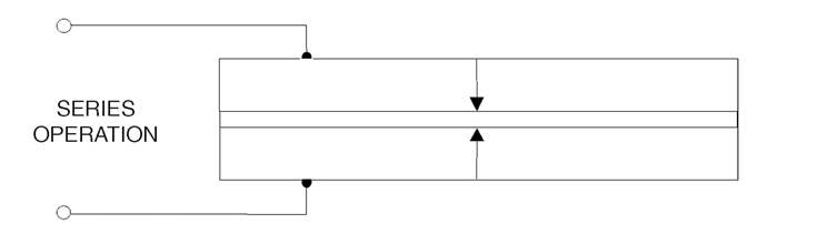
There are two standard polarization configurations for the two-layer bending generator construction: series and parallel. These are illustrated in Figure 17. Both the series and parallel elements are limited to electric fields below the coercive field (~ 475 V/mm for PZT-5A).
The bender poled for series operation (which we refer to as “X poled”) is the simplest and most economical. As depicted in Figure 24, it requires two connections to the outside surfaces of the piezoceramic layers which are electrically in series. Thus, their voltages add. It is characterized by a lower capacitance, lower current, and higher voltage.
As depicted in Figure 25, the bender poled for parallel operation (which we refer to as “Y poled”) requires three electrical connections. The third connection accesses the center shim of the bender, requires an extra manufacturing step and has a somewhat higher production cost. Voltage is developed across the individual layers, and since they are wired electrically in parallel their charges (or currents) add. The parallel bender is characterized by higher capacitance, higher current, and lower voltage.

Standard mounts for bending generators are illustrated in Figure 26 and fall into two general categories. The first category has power input at one end and is mounted at the other. Known as the cantilever mount, it provides maximum compliance. The second category, known as the simple beam mount, has power input at the center and is mounted at the ends. The simple beam mount allows the ends to move in and out as well as rotate but fixes their vertical position. Compared to the cantilever mount, the simple beam mount provides increased stiffness and frequency. For high frequency-resonant applications, power dissipation at the mounts can be minimized by using nodal mounts. The nodes are evenly spaced, .55L apart, where L is the length of the beam. Ridgid clamping at both ends is often considered by novice designers for expedience (e.g. by bonding to the edges of a cutout or clamping as illustrated in Figure 26). In theory if the end clamps are perfectly rigid the motion at the center of the beam will be exactly zero. In practice no material is perfectly rigid, so typically the designers are left to puzzle out why the actuator is only making 1/10 the expected excursion.

The following equations for bending generators are more accurate than those in Table 4 in so far as they take into account the center shim. They can be used to: 1.) verify that the bending generator is operating properly, and 2.) scale the dimensions of the experimental generator to define the dimensions of the final design, or vice versa. The relations below were taken from an article titled “Flexure Mode Piezoelectric Transducers” by Carmen Germano, published in IEEE Transactions on Audio and Electroacoustics, Volume AU-19, No.1, March 1971.


The short-circuit charge, Qs, is usually twice the required operating charge.
 |
(2.1) |
 |
(2.2) | |
where 
|
The open circuit voltage, Vo, is usually twice the required operating voltage.
 |
(2.3) |
 |
(2.4) | |
where 
|
 |
(2.5) |
 |
(2.6) | |
| where ~ 500x10-6 is the maximum recommended strain limit in tension |
 |
(2.7) |
 |
(2.8) |
Transducers which convert mechanical energy to electrical energy (i.e. generators) come in a wide range of shapes and sizes, each having their own characteristic voltage-charge output capabilities as well as input force - displacement characteristics.
On the mechanical input side, the design process involves correctly matching the volume and stiffness of the generator to the target input force. The stiffness of the transducer determines how much mechanical energy gets transferred into the transducer from the source force. The piezoceramic material properties determine what percentage of this energy will be available as electrical energy. The total volume of piezoceramic sets an upper limit on amount electrical energy available for use.
While there is no simple way to estimate the electrical power that can be extracted from any given piezo harvester construction, some intuition of the maximum extractable power in the “transverse mode” from a 10mm square patch of ceramic itself can be gained by inspection of Figure 28.

Figure 3.1. Electrical power available from 1 cm x 1 cm PZT-5A patch in transverse mode for applied sinusoidally varying uniform strain
The basis for this graph is as follows:
Piezo material: PZT-5A
Size of harvester: 10mm x 10mm x 0.25mm
Electrodes: full coverage of both 10mm x 10mm faces
Polarization: Through the 0.25mm thickness
Mechanical input: dynamic (i.e. +/-) uniform strain applied on a 10mm x .025mm edge over a range of frequencies
Electrical output: taken between the two electrodes with imaginary perfect circuitry
Strain rather than stress is utilized as the independent applied mechanical input for two reasons:
- Piezoceramics' mechanical dynamic excitation limits can be easily approximated as +/-500E-06 meters/meter (i.e. 500 microstrain). This figure is a commonly used as a rule of thumb arising from the tensile limit of the materials and is incorporated into the graph as an upper limit.
- It is far easier experimentally to measure surface strain on various constructions and infer the interior stresses than to measure stress directly.
The Y axis of this graph shows the applied +/- uniform strain, the X axis shows the frequency of sinusoidal strain application. The lines are “contours of constant electrical power output” showing the trade-off between applied strain and applied frequency for this small sample of ceramic. For the same size of ceramic, low frequency vibrational environments will require devices designed to apply higher stresses than high frequency vibrational environments.
No practical design will achieve this upper limit. Strains/stresses are seldom uniform, never applied without loss, and electronic circuits are never perfect. Harvester design work consists mainly of exploring various compromises. Consider as an example the cantilevered bimorph beam. When the beam is bent, the average strain in the ceramic layers is exactly half the surface strain, so when the surface is at its limit the voltage on the plates will only be 1/2 the achievable max, and the energy stored in the capacitance of the layer will therefore be only 1/4. But it gets worse! During vibration the distribution of strain on the surface is not uniform along the length of the beam - its high near the cantilever point and drops off going out to the tip, reducing the limiting output by perhaps another 1/4 to 1/3. So, the price of the convenience of the bimorph is that its electrical output for every 10mm square of device will really be only about 1/16 what is on our graph. WARNING: power outputs may be smaller than they appear!
On the electrical output side, the design process centers on delivering the total electrical energy to the load at a specific voltage-current combination (e.g. 5V @ .05 mA rms). In principle this determination is independent of the input design and consists primarily of dividing up the piezoceramic into a number of layers which get wired in parallel.
As a general-purpose reference guide, Table 4 shows the spectrum of generator transducers commonly considered in piezoelectric applications. This can be accomplished after the energy design by subdividing the volume of ceramic into layers (with parallel wiring). The result is a multi-layer design capable of delivering the same energy at a lower voltage and a higher current.


The equations for charge and voltage as functions of either input force or displacement shown in Table 4 are based on linear relationships and low signal values for their piezoelectric coefficients.
Table 4 also provides the equations for determining the fundamental resonant frequency. The expression:
 |
(3.1) |
common to all calculations of frequency represents the velocity of sound in piezoceramic along the associated axis of interest. The time it takes for an element to actuate is related to how quickly a pressure wave can travel through the medium.
For devices which may be constructed of multiple material layers (such as benders), the modulus, Y, and density, ρ, are determined by be following relations:
 |
(3.2) |
 |
(3.3) |
The mechanical energy stored by a piezo device acted upon by a force is:
 |
(3.4) |
where Em is the stored mechanical energy in Joules, Y is Young’s modulus in N / m2, S is the induced strain in m / m, and V is the volume of piezoceramic in m3.
The electrical energy stored by a piezo device is:
 |
(3.5) |
where Ee is the stored electrical energy in Joules, C is the capacitance in Farads, and Vo is the open circuit voltage.