
Piezo Transducer Overview
Transducers convert one form of energy to another. Piezo actuators convert electrical energy to mechanical energy. This is why they are referred to as “motors” (often linear motors). Piezo sensors convert mechanical energy into electrical energy. This is why they are referred to as “generators”. In most cases, the same element can be used to perform either task.
Single sheets: can be energized to produce motion in the thickness, length, and width directions. They may be stretched or compressed to generate electrical output.
Thin 2-layer elements are the most versatile configuration of all. They may be used like single sheets (made up of 2 layers), they can be used to bend, or they can be used to extend. “Benders” achieve large deflections relative to other piezo transducers. “Extenders”, being much stiffer, produce smaller deflections but higher forces.
Multilayered piezo stacks can deliver and support high force loads with minimal compliance, but they deliver small motions.
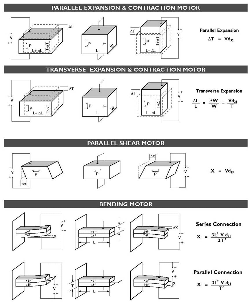
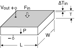
When an electric field having the same polarity and orientation as the original polarization field is placed across the thickness of a single sheet of piezoceramic, the piece expands in the thickness or "longitudinal" direction (i.e. along the axis of polarization) as shown in Figure-1. At the same time, the sheet contracts in the "transverse" direction (i.e. perpendicular to the axis of polarization) as shown in Figure-2. When the field is reversed, the motions are reversed.


Sheets and plates utilize this effect. The motion of a sheet in the thickness direction is extremely small (on the order of tens of nanometers). On the other hand, since the length dimension is often substantially greater than the thickness dimension, the transverse motion is generally larger (on the order of microns to tens of microns) . The transverse motion of a sheet laminated to the surface of a structure can induce it to stretch or bend, a feature often exploited in structural control systems.
2 -layer elements can be made to elongate, bend, or twist depending on the polarization and wiring configuration of the layers. A center shim laminated between the two piezo layers adds mechanical strength and stiffness, but reduces motion.
"2-layer" refers to the number of piezo layers. A "2-layer" element actually has nine layers, consisting of: four electrode layers, two piezoceramic layers, two adhesive layers, and a center shim. The two layers offer the opportunity to reduce drive voltage by half when configured for parallel operation.
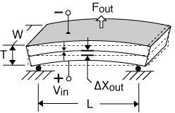
Extension Motors:
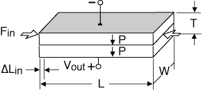
A 2-layer element behaves like a single layer when both layers expand (or contract) together. If an electric field is applied which makes the element thinner, extension along the length and width results. Typically, only motion along one axis is utilized, as demonstrated in Figure-3. Extender motion on the order of microns to tens of microns, and force from tens to hundreds of Newtons is typical.
For extension motors of the same thickness:
Free Deflection (Xf) L
Blocked Force (Fb) W
Resonant Frequency (Fr) I / L
Capacitance (C) L x W
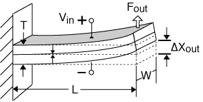
Bending Motors:
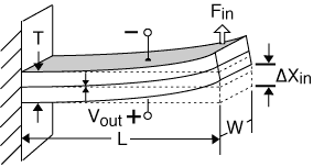
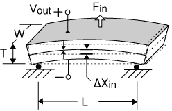
A 2-layer element produces curvature when one layer expands while the other layer contracts. These transducers are often referred to as benders, bimorphs, or flexural elements. Bender motion on the order of hundreds to thousands of microns, and bender force from tens to hundreds of grams, is typical. Figures-4, 5 and 6 show several common bending configurations. The variety of mounting and motion options make benders a popular choice of design engineers.
For standard cantilevered benders of the same thickness:
Free Deflection (Xf) L2
Blocked Force (Fb) W / L
Resonant Frequency (Fr) I / L2
Capacitance (C) L x W
Characteristics: End takes on an angle. Easy to mount.

To convert standard cantilever performance to "S" bender performance:
Free Deflection (Xf) = 1 / 2 x cantilever motion
Blocked Force (Fb) = 1 / 2 x cantilever force
Resonant Frequency (Fr) = same as cantilever frequency
Capacitance (C) = same as cantilever capacitance
Characteristics: end moves up and down in a parallel plane
To convert cantilever performance to simple beam performance:
Free Deflection (Xf) = 1 / 4 X cantilever motion
Blocked Force (Fb) = 4 X cantilever force
Resonant Frequency (Fr) = 3 X cantilever frequency
Capacitance (C) = same as cantilever capacitance
Characteristics: center moves up and down in a parallel plane.
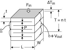
Any number of piezo layers may be stacked on top of one another. Increasing the volume of piezoceramic increases the energy that may be delivered to a load. As the number of layers grows, so does the difficulty of accessing and wiring all the layers.
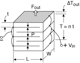
Stack Motors:
The co-fired stack shown in Figure-7 is a practical way to assemble and wire a large number of piezo layers into one monolithic structure. The tiny motions of each layer contribute to the overall displacement. Stack motion on the order of microns to tens of microns, and force from hundreds to thousands of Newtons is typical.
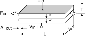
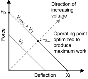
Piezoelectric actuators are usually specified in terms of their free deflection and blocked force. Free deflection (Xf) refers to displacement attained at the maximum recommended voltage level when the actuator is completely free to move and is not asked to exert any force. Blocked force (Fb) refers to the force exerted at the maximum recommended voltage level when the actuator is totally blocked and not allowed to move. Deflection is at a maximum when the force is zero, and force is at a maximum when the deflection is zero. All other values of simultaneous displacement and force are determined by a line drawn between these two points on a force versus deflection line, as shown in Figure-8. Generally, a piezo motor must move a specified amount and exert a specified force, which determines its operating point on the force vs. deflection line. An actuator is considered optimized for a particular application if it delivers the required force at one half its free deflection. All other actuators satisfying the design criteria will be larger, heavier, and consume more power.
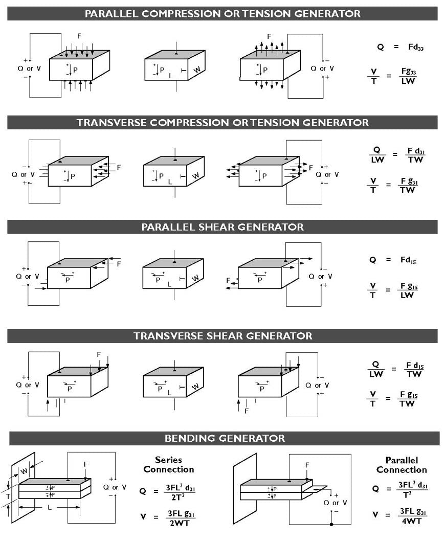
When a mechanical stress is applied to a single sheet of piezoceramic in the longitudinal direction (parallel to polarization), a voltage is generated which tries to return the piece to its original thickness. Similarly, when a stress is applied to a sheet in a transverse direction (perpendicular to polarization), a voltage is generated which tries to return the piece to its original length and width. A sheet bonded to a structural member which is stretched or flexed will induce electrical generation. Figure-9 and Figure-10 show longitudinal and transverse generators respectively.

Applying a mechanical stress to a laminated two layer element results in electrical generation depending on the direction of the force, the direction of polarization, and the wiring of the individual layers.
For extension generators of the same thickness and force loading:
Deflection Limit (Xl) L
Open Circuit Voltage (Voc) (Xl) / L = I
Closed Circuit Current (Icc) L x W
Extension Generators:
When a mechanical stress causes both layers of a suitably polarized 2-layer element to stretch (or compress), a voltage is generated which tries to return the piece to its original dimensions. Essentially, the element acts like a single sheet of piezo. The metal shim sandwiched between the two piezo layers provides mechanical strength and stiffness while shunting a small portion of the force.
For Bending Generators of the same thickness and force loading:
Deflection Limit (xl) L2
Voc, Open Circuit Voltage (xl) / L2 = I
Closed Circuit Current (Icc) L x W
Bending Generators:
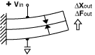
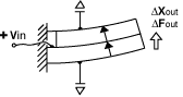
When a mechanical force causes a suitably polarized 2-layer element to bend, one layer is compressed and the other is stretched. Charge develops across each layer in an effort to counteract the imposed strains. This charge may be collected as observed here.
To convert cantilever to simple beam generator performance
for the same thickness and force load):
Voc = 1/4X cantilever voltage
Icc = 1/4X cantilever current
To convert cantilever to simple beam performance
for the same thickness and deflection):
Voc = 4X cantilever voltage
Icc = 4X cantilever current
Applying a mechanical stress to a laminated two layer element results in electrical generation depending on the direction of the force, the direction of polarization, and the wiring of the individual layers.
Stack Generators:
The stack,shown in Figure-14, comprises a large number of piezo layers, and is a very stiff structure with a high capacitance. It is suitable for handling high force and collecting a large quantity of charge efficiently.
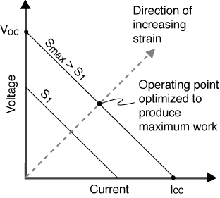
Piezoelectric generators are usually specified in terms of their closed-circuit current (or charge) and open-circuit voltage. Closed-circuit current, ICC, refers to the total current developed, at the maximum recommended strain level and operating frequency, when the charge is completely free to travel from one electrode to the other, and not asked to build up voltage. Open-circuit voltage, Voc, refers to the voltage developed at the maximum recommended strain level, when charge is prohibited from traveling from one electrode to the other. Current is at a maximum when the voltage is zero, and voltage is at a maximum when the charge transfer is zero. All other values of simultaneous current and voltage levels are determined by a line drawn between these points on a voltage versus current line, as shown in Figure-15. Generally, a piezo generator must deliver a specified current and voltage, which determines its operating point on the voltage vs. current line. Maximum power extraction for a particular application occurs when the generator delivers the required voltage at one half its closed circuit current. All other generators satisfying the design criteria will be larger, heavier, and require more power input.
DYNAMIC VERSUS STATIC SENSOR OPERATION
Piezo elements are excellent for dynamic or transient motion and force sensing. They are used as strain gages for easy and rapid determination of dynamic strains in structures due to their extremely high signal/noise ratios (on the order of 50 times that of wire strain gages). They require no power input since they generate their own power. In fact, this is why they are now considered useful as energy harvesting and scavenging devices. They are small enough that they will not materially affect the vibrational characteristics of most structures.
On the other hand, piezo elements are generally poor at measuring static or slowly changing inputs due to charge leakage across their electrodes or through monitoring circuits.
Series Operation:
Series operation refers to the case where supply voltage is applied across all piezo layers at once. The voltage on any individual layer is the supply voltage divided by the total number of layers. A 2-layer device wired for series operation uses only two wires (one attached to each outside electrode), as shown in Figure-17.
Parallel Operation:
Parallel operation refers to the case where the supply voltage is applied to each layer individually. This means accessing and attaching wires to each layer. A 2-layer bending element wired for parallel operation requires three wires (one attached to each outside electrode and one attached to the center shim), as shown in Figure-18. For the same motion, a 2-layer element poled for parallel operation needs only half the voltage required for series operation.
X-Poled:
Refers to the case where the polarization vectors for each of the 2 layers point in opposite directions, generally, towards each other.

Y-Poled:
Refers to the case where the polarization vectors for each of the 2 layers point in the same direction.