

Transducers which convert electrical energy to mechanical energy (i.e., motors) come in a wide range of shapes and sizes, each having their own characteristic force-displacement capabilities. Stiff (low compliance) transducers provide tremendous force but tiny motion. On the other hand, highly compliant transducers provide substantial motion but small force.
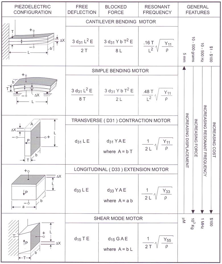
As a general-purpose reference guide, Table 3 shows the spectrum of motor transducers commonly considered in piezoelectric applications. The equations for displacement, force, and resonant frequency, are based on linear relationships and low signal values of their piezoelectric strain coefficients.
Piezoelectric actuators are usually specified in terms of their free deflection and blocked force. Free deflection, Xf, refers to displacement attained at the maximum recommended voltage level when the actuator is completely free to move and is not asked to exert any force. Blocked force, Fb, refers to the force exerted at the maximum recommended voltage level when the actuator is totally blocked and not allowed to move. Deflection is at a maximum when the force is zero, and force is at a maximum when the deflection is zero. All other values of simultaneous displacement and force are determined by a line drawn between these points on a force versus deflection line, as shown in Figure 4.
Generally, a piezo motor must move a specified amount and exert a specified force, which determines its operating point on the force vs. deflection line. Work is maximized when the deflection performed permits one half the blocked force to be developed. This occurs when the deflection equals one half the free deflection.

For cantilevered bending motors, Xf is determined by measuring the tip deflection after energizing, and Fb is measured by holding a force gauge in position against the tip during energization.
For “on demand” actuator applications, it is useful to know how fast an actuator will operate. The fundamental resonate frequency, Fr, is a guidepost towards answering this question. A piezo actuator can follow a sinusoidal signal up to its resonant frequency. Beyond this point, its inertia inhibits it from keeping up with electrical excitation. From a practical standpoint, it’s a good idea to limit operation to ~3/4 Fr. The response time, tr, for an actuator to travel through its full range, for bipolar operation (from 0 to positive voltage, then to negative voltage, and back to 0) is ¼ cycle. Thus,
 |
(1.1) |
For example, an actuator driven by a bipolar power supply, and having a resonant frequency of 500 Hertz, has a response time of 0.67 milliseconds. Any mass added to the end of the actuator will lengthen the response time.
For those applications which require the piezo actuator to hold its position accurately for a long time, an understanding of hysteresis and creep is important. For dynamic applications, where position is changing continuously, these issues are less critical.
Hysteresis: When a polycrystalline piezoelectric body is deformed, part of the mechanical energy is stored as elastic strain energy, and part is dissipated as hear during small internal sliding events. Hysteresis appears as an offset between the position path traveled during the application and removal of the excitation field. The size of the offset depends on the field level, the cycle time, and the materials used. It is often specified as a percentage of the total deflection achieved, and ranges from .1% to 10%. Hysteresis is a consideration wherever high frequencies (> 1 kHz) are concerned because of heat accumulation within the piece after each cycle of operation. This is especially the case for low voltage piezo stacks made of high strain material. This can lead to excessive temperatures if care is not taken in the design. Other portions of the piezoelectric system also contribute to losses, such as adhesive bonds, mounts, and attachments. These show up in ultrasonic designs.
Creep (or Drift): Creep is the result of time dependent plastic deformation. Usually it is not a concern under oscillating drive conditions, however any high-level DC voltage application should pay close attention to creep. After voltage has been applied to a piezoelectric actuator, the deflection increases with time. For moderate drive levels (> 10 volts/mil), the creep rate decreases with time. However, as the drive level increases (> 20 volts/mil), the creep rate accelerates. Upon removal of the drive voltage, the piece retains a set, a portion of which is irreversible even after a long relaxation period. At high drive levels (> 30 volts/mil), creep many proceed to the point where the piece finally cracks. Increased temperature exacerbates creep.
When excessive creep is encountered, certain strategies may be required, such as stops to limit excessive travel, or closed loop feedback control to lock in a desired position.
Figure 5 demonstrates both typical hysteresis and creep behavior of a blending element. When a piece has been at rest for some length of time (~1 day), it will reside at its equilibrium position, 0. Upon initial energization, it will move to position 1. After de-energization it will go to position 2. If it is allowed to rest for a sufficient length of time (~1 day) it will revert back to position 0 again. However, if it is reenergized immediately, it will follow path 2-1. When the piece is energized and left on, it will creep along the path 1-1’, and come to rest at position 2’ after de-energization. A piece operating in AC mode will follow path 1-2-3-4-1.

An ideal mount permits the normal distortion of the entire active portion of the motor element, while at the same time preventing motion in certain directions at the mounting point or points. Generally piezo motors are either bonded, clamped, or spring loaded to their mounting points. Mounts introduce some mechanical damping into the system since some of the energy from the motor distorts the mount itself. This may or may not be desirable.
Mechanical resonance is a manifestation of the trading back and forth of kinetic energy (moving mass) and potential energy (elasticity) in an oscillating body. At certain frequencies, known as resonances, the amount of stored energy becomes very large compared to the excitation energy.
This phenomenon can be useful for achieving large deflections at low voltages, and for obtaining high efficiency. Piezo fans and ultrasonic devices utilize this property. Because of the high amplitudes exhibited at resonance, care must be taken to overstrain and crack the actuator.
The resonant frequencies of a piezo motor depend on its dimensions, material properties, and the manner of mounting. The cantilever beam element has the lowest fundamental (first) resonant frequency per unit length of all configurations and mounting schemes. Equations for determining the fundamental resonant frequencies for several motor configurations are shown on Table 3 on page 16. These frequencies apply to unloaded elements only. Attachments to the element will add to the resonating mass and lower the resonant frequency.
Up to resonant frequency, the deflection of a piezoelectric bending element is nearly independent of frequency and proportional to the operating voltage. Around the resonant frequency, deflection rises rapidly to a multiple of its normal value. The amplitude and narrowness of the resonance peak depend on the internal and external losses acting on the actuator. Above resonance, deflection decreases steadily with the square of the frequency. First resonance marks the limit of the usable frequency band for quasi-static actuators. For resonant applications, the useable frequency range is limited to a small band around the useful resonant modes.
Piezoceramic is very strong in compression but weak in tension. Bending elements always have one side in compression and the other side in tension, where the magnitude of stress increases linearly from the midplane to the outside surface. Therefore, the element is always limited by the maximum recommended tensile strength, generally considered to be in the range of 20-35 x 106 Newtons/meters2. From a strain point of view, the ceramic should not be allowed to strain more than 500 x 106 meter/meter.
A piezoelectric actuator operating below its fundamental resonance can be treated as a capacitive load. The circuit must supply charge to cause a motion and must withdraw charge to cause a retraction (i.e., charge applied to the device does not bleed off internally). When held motionless in any position, piezoelectric actuators draw negligible current, typically much less than a microamp.
A piezoelectric actuator operating near resonance can be modeled as a capacitor (having a value equal to the transducer capacitance) with a resistor in parallel (typically 10 to 100 ohms). The power dissipated by this resistance represents the work which the actuator does on its environment. The drive circuit must have sufficient current capacity to maintain the desired voltage on the resistor.
Instantaneous charging or discharging of piezoelectric actuators causes acoustic shockwaves within the piezoceramic which can lead to localized stress concentrations and fractures. Therefore, the peak current to any actuator must be limited. One simple method places a protection resistor in series with the actuator, the value of which can be estimated using the following relation:
 |
(1.2) |
For a series operated cantilevered bending element, substituting for C and Fr:
 |
(1.3) |
This essentially limits operation to a frequency region below the fundamental resonance.
Piezoelectric bending elements can generate high voltages (>100 volts) under external vibration, shock, or temperature shifts. If these conditions are expected, the drive circuitry of the output stage must be protected against transient voltages of all polarities.
The outer electrode surfaces of certain motor elements are electrically “live” in many configurations. For product or experimental safety, consideration should be given to insulating or shielding the electrodes, mount, and power take-off sections of the motor element.
The highest value of applied electric field is determined by electrical breakdown occurring either through the body of the piezoceramic sheet or over the its edges. Piece of dust and debris adhering to edges can initialize edge discharge at fields as low as 400-800 volts/mm. However, the discharge arc vaporizes the debris, thereby cleaning itself. A number of these edge-debris arcs may occur during the initial energization or the bending motor, but they will not occur again. Continuous breakdown occurs around 3,000-4,000 volts/mm, usually at impurity or defect regions within the bulk of the material. This can lead to a short circuit across the sheet due to vapor deposition of electrode or shim material near the site of arcing. A current limiting resistor or in-line fuse is recommended when excessive electric fields are used.
The bulk resistivity of piezoceramic is ~1012 Ω-cm. Therefore, electrical losses are minimal under static or low frequency operation. However, dielectric losses are significant under cycled operation and can lead to heating under high frequency/high power operations. The loss tangent, the ratio of series resistance to series reactance, for PZT-5A is ~0.015.
For each piezoceramic material there is a critical temperature, known as its Curie point, which represents its maximum operating temperature before suffering a permanent and complete loss of piezoelectric activity. In practice, the operating temperature must be limited to some value substantially below the Curie point because at elevated temperatures depoling is greatly facilitated, the aging process is accelerated, electrical and mechanical losses increase, and the maximum safe stress is reduced. As a rule of thumb, a temperature equal to one half the Curie temperature is considered the maximum safe operating temperature.
Piezoelectric properties are strongly temperature dependent, and thermal dependence varies markedly from one material to the next. Figure 6 demonstrates the temperature dependence of K3 and d31 for PZT-5A.

An electric field is induced on the electrodes of a piezo motor when it is exposed to a thermal change. The induced field is
 |
(1.4) |
Where α is the pyroelectric coefficient in units of coulombs /m2 °C, ΔT is the temperature change, K3 is the relative dielectric constant in the poling direction, and ε0 is the permittivity of free space. It should be noted that a depoling voltage will be developed across a layer of piezoceramic when the temperature drops. This can happen during processing, testing, and normal usage. If a temperature drop is sufficient, over a time interval which is too short to allow charge to leak away, a voltage greater than the coercive field can result. This can degrade the original polarization causing reduced performance. It is always good practice to short circuit the electrodes of any piezo device during a cool down procedure.
One must account for thermal displacements over the temperature range anticipated. The actuator must be capable of compensating for thermal displacements and still have a useful motion range.
In addition, differential thermal expansions of adjacent assembly parts will cause moments and warping. The standard bending motor element has a symmetrical construction. Distortion due to thermal excursion should be negligible. However, care should be taken in the design of the mount or any other attachments not to introduce thermal distortion. This is facilitated by properly matching the thermal expansion coefficients of adjacent members to that of the ceramic element. The coefficient of thermal expansion of PZT-5A is ~4 µm/m °C.
The low signal values of the strain coefficients for operation at 4.2 K are reduced by a factor of 5-7 times. The value of the coercive field increases substantially, however. Cycling the transducer between these temperature extremes does not seem to affect them adversely.
Because piezo actuators are solid state devices, they lend themselves to high vacuum operation. However, several issues should be understood. First, voltage should not be applied to the electrodes during the vacuum pump-down process because of the low insulation resistance of air and nitrogen between the range of 10 to 0.1 torr. Arcing between electrodes is possible within this pressure range. Secondly, outgassing of the part is possible depending on construction materials. Motors to be used in high vacuum environments should have small cross sections of outgassing materials (primarily the adhesive). If bake-out is necessary, the transducer will have to be built to withstand solvents and bake-out temperatures.
As mentioned earlier, under adverse conditions piezoelectric properties may degrade, vanish completely, or be flipped around 180°. A strong electric field applied to a piezoceramic in a sense opposite to the original poling voltage will tend to cause depoling. The field strength necessary to initiate depoling depends on the material, duration of application, and temperature, but is typically in the range of 475 volts/mm at 20°C for PZT-5A under static conditions. Alternating fields may also degrade the piezoceramic, but the peak field level is higher because the duration is shorter before the field is reversed. A peak field of 600 volts/mm may be tolerated for 60 Hz operation at 20°C.
When the mechanical stress on a piezoceramic element becomes too high, again there is a danger of degrading the piezoelectric properties. Generally, compressive or hydrostatic stress levels of -50x106 N/m2 are required to degrade PZT-5A if no other degrading influences are present.
Piezoelectric properties change gradually with time. The changes tend to be logarithmic with time after the original polarization. Therefore, the rate reduces rapidly with time. Aging depends on the ceramic material, manufacturing process, and ambient conditions such as temperature, vibration or shock. Pieces may be heated for a specific time to accelerate the aging process.
The most common type of piezoelectric bending motor is composed of two layers of piezoceramic bonded to a thin metal shim sandwiched in the middle. The construction and typical dimensions of the 2-layer elements in this kit are shown in Figure 7.

The application of voltage to the element is analogous to the application of heat to a bimetallic strip. The voltage across the bender element forces one layer to expand, while the other contracts, as depicted in Figure 8. The result of these physical changes is a strong curvature and large deflection at the tip when the other end is clamped. The tip deflection is much greater than the change in length of either ceramic layer.
Bending motors exhibit unique properties. They may be energized proportionately and be held in the energized position with negligible consumption of energy and generation of heat. They may be operated over billions of cycles without wear or deterioration. Their low profile allows their use in very restricted locations.

There are three standard polarization configurations for the two-layer bender construction: series, parallel, and single plate (monomorph). These are illustrated in Figure 9. Both the series and parallel elements are limited to electric fields below the coercive field (~ 475 V/mm for PZT-5A).
The bender poled for series operation is the simplest and most economical. It requires two connections to the outside surfaces of the piezoceramic layers which are electrically in series. It is characterized by a lower capacitance, lower current, and higher voltage.
The bender poled for parallel operation requires three electrical connections. The third connection accesses the center shim of the bender, requiring an extra manufacturing step and therefore a higher cost. Voltage is applied across the individual layers. The advantage of the parallel bender is that its deflection per volt is twice that of a series bender. However, the maximum deflection is the same for both. The parallel bender is characterized by higher capacitance, higher current, and lower voltage.
In motor applications requiring extra deflection, a third alternative is available. In this case a bender poled for series operation is used with three electrical connections. Voltage is applied to either layer of piezoceramic in the direction of polarization. Usually only one side is energized at a time. The excitation field may exceed the coercive field since there is no concern for depolarization. Fields as high as 1,500-2,000 volts/mm (the level where arcing starts to occur near the edges) may be applied.

Standard mounts for bending motors are illustrated in Figure 10 and fall into two general categories. The first category has power taken off at one end and is mounted at the other. Known as the cantilever mount, it provides maximum compliance and deflection. The second category has power taken off at the center and is mounted at the ends. The simple beam mount allows the ends to move in and out as well as rotate but fixes their vertical position. Compared to the cantilever mount, the simple beam mount produces reduced deflections, increased forces, and increased frequency. For high frequency-resonant applications, power dissipation at the mounts can be minimized by using nodal mounts. The nodes are evenly spaced, .55L apart, where L is the length of the beam. The beam may also be rigidly clamped at both ends, although this results in a significant proportion of the beam being constrained.

The “Bending Motor Equations” describe non-linear behavior and take into account the center shim. They can be used to estimate the motion and blocking force of 2-layer bending elements based on their dimensions and material property values. The relations below were developed by C.P. Germano of Vernitron Piezoelectric, with minor modifications by PIEZO.COM.
Definition of terms:
L = Total Length of the bending motor (m)
Lc = Cantilever length (m)
T = Total thickness of bending motor (m)
δ = Thickness of center shim and adhesive layers (m)
tc = Thickness of a single layer of piezoceramic (m)
b = Width of bending motor (m)
d31 = Piezoelectric transverse strain coefficient (m/V)
E = Electric field strength (V/m)
E (series operation) = Voltage /2tc
E (parallel operations) = Voltage / tc
Y = Young’s modulus of elasticity (N/m2)

The free deflection, Xf, is usually twice the required operating deflection.
 |
(2.1) | |
where 
|
The blocked force, Fb, is usually twice the required operating force.
 |
(2.2) | |
|
where
|
 |
(2.3) |
~500x10-6 is the maximum recommended strain limit in tension.
 |
(2.4) |
 |
(2.5) |
 |
(2.6) |

Free Deflection: Multiply the cantilever Xf by ¼
Blocked Force: Multiply the cantilever Fb by 4
Resonant Frequency: Multiply the cantilever Fr by 8
Surface Strain: Multiply the cantilever S by 4
Capacitance: Same as cantilever for both series and parallel operation